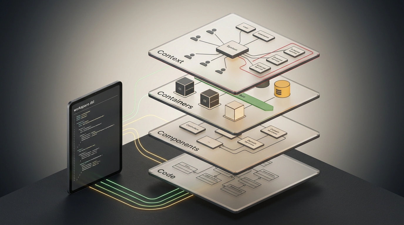
Think back to what an architecture discussion usually looks like in an average product team. Someone opens an online whiteboard in Miro or Confluence, where a dozen and a half colorful rectangles are drawn with labels like "Auth Service", "Data Bus", and "Backend". Arrows point in every direction at once: some show network calls, others show data flow, and still others show deployment dependencies. When asked "What's inside the Auth Service?", the team lead sighs and says: "There's legacy Express code, half of it was rewritten in Go, it's not on the diagram, you have to check prod."
Three months later, the project expands, new microservices appear, and the old picture turns into a useless historical monument. Developers stop looking at the documentation because it lies, and architectural decisions are made on the fly right inside repository branches.
In the early 2000s, the industry tried to fight this problem with the UML (Unified Modeling Language) standard created by the OMG consortium. Yet the academic complexity of UML—with its fourteen diagram types and strict arrow notations—suffocated in the Agile era: teams simply couldn't keep heavy documents up to date. British architect Simon Brown proposed an ingeniously simple way out: the C4 model, inspired by the zoomable map principle of Google Maps.
And today, this approach is experiencing a second birth thanks to the Architecture as Code (AaC) paradigm and the Structurizr DSL language. In a series of deep studies and lectures, Ukrainian engineer Timur Shemsedinov showed how C4 solves a fundamentally new challenge of 2026: turning into a structured coordinate system for AI agents (Claude, Cursor, Copilot, Windsurf), saving teams from explosive token consumption and architectural hallucinations.
Let's unpack this multi-layered mechanic from fundamental abstractions to practical code and integration with neural networks.
From UML Bureaucracy to Google Maps Scale: Origins of the C4 Model
To appreciate the elegance of C4, you need to step back for a second into the RUP (Rational Unified Process) era of the late 1990s. The engineering paradigm of those years demanded "designing everything before the first line of code." Analysts spent months drawing sets of UML: Use Case Diagrams, Sequence Diagrams, Component Diagrams, Deployment Diagrams.
But when the industry shifted to two-week sprints, continuous delivery, and microservices, three systemic flaws emerged in UML:
- Excessive academicism: Instead of answering "how do we deliver an order," engineers in reviews argued about the difference between association, aggregation, and composition on a class diagram.
- Lack of a unified end-to-end hierarchy: UML had no standard rule for mapping a company's high-level business goal to a specific database. Diagrams existed in isolation without forming a cohesive system.
- Unintelligibility for stakeholders: A product manager looking at a UML Deployment Diagram with ports and artifacts understood nothing at all, while a developer looking at a use case diagram couldn't see the tech stack.
Simon Brown noticed a simple analogy: how does a person navigate the physical world? You open Google Maps on your smartphone. On the first screen, you see continents and countries. That lets you understand where on the globe you even are. Zoom in—region borders, major cities, and highways appear. Zoom in more—streets, house numbers, and turns.
The C4 model transferred this multi-level lens into software engineering. Brown defined four strict levels of abstraction:
- Context (System Context);
- Containers (Containers);
- Components (Components);
- Code (Code).
Each level answers the questions of a strictly defined audience and cuts out technical noise unnecessary at that scale.
Four Levels of C4 Abstraction: Context, Containers, Components, Code
Let's dissect each of the model's four layers in detail.
1. Level 1: System Context Diagram
This is a bird's-eye view. At the center of the diagram sits the target software system as a single black box. Around it are external entities: users (actors, roles) and external systems it interacts with (payment gateways, CRMs, email providers, government registries).
The ironclad rule of the first level: no technical details. Writing "PostgreSQL", "Kafka", "gRPC", "Go", or "Linux" here is strictly forbidden. Only business roles and the essence of the data exchanged: "Customer places an order", "Payment service charges funds". The company CEO, an investor, and a new intern on day one of onboarding should all understand this diagram at first glance.
2. Level 2: Container Diagram
We take the first zoom step and "look inside" the software system. And here it's crucial not to fall into a terminological trap: in the C4 model, a "container" is not a Docker container or a Kubernetes Pod.
In Simon Brown's definition, a container is any separately deployable or executable unit of software that stores data or executes code:
- A client-side Single Page Application in the browser (React, Vite);
- A mobile app (iOS / Android on Flutter);
- A server-side API microservice (Go, Node.js, or Java);
- A relational database (PostgreSQL);
- A distributed message broker (Apache Kafka);
- Object storage (MinIO / S3).
The container diagram is the favorite working blueprint of architects, DevOps engineers, and backend developers. It shows the high-level topology: which services exist, what each one is responsible for, what technologies they are built on (for example, NestJS / TypeScript, PostgreSQL 16), and which protocols they use to communicate (JSON/HTTPS, gRPC, Kafka Protocol).
3. Level 3: Component Diagram
The next zoom level: we take one specific container (say, the orders API service) and reveal its internal structure as logical modules and components: controllers, business logic services, external integration adapters, data access repositories.
Here lies Brown's most important recommendation: you don't need to draw component diagrams for every service in the company. If a service is a simple 500-line CRUD module, modeling its components is a waste of time. A component diagram is created only for architecturally complex, high-load, or non-trivial services where it matters to lock down clean architecture layer separation or fault-tolerance patterns.
4. Level 4: Code Diagram
This is the ultimate level of detail: UML class diagrams or Entity-Relationship (ER) diagrams showing interfaces, methods, and dependencies in code.
Modern engineering consensus is crystal clear: Level 4 should categorically never be modeled manually. Classes and function signatures change with every commit. Manually maintaining code in architectural diagrams goes stale immediately. If a class diagram is genuinely needed, it should be auto-generated from the AST by a compiler or IDE tools.
Architecture as Code: A Single Source of Truth Based on Structurizr DSL
When teams start adopting C4, the first mistake is usually trying to draw these diagrams in graphical editors like Draw.io, Lucidchart, or Visio. That is a dead-end path.
Imagine: a microservice's name changed, or a payment gateway switched from REST to gRPC. If diagrams are drawn by hand, the architect has to open the context diagram, the container diagram, and three component diagrams and manually retype text in graphical boxes. Human error is inevitable: on one diagram the service has the new name, on another the old protocol remains, and on a third someone forgot to delete an arrow.
The Architecture as Code (AaC) paradigm draws a fundamental boundary between the system model and its visual views.
The Structurizr DSL language, developed by Simon Brown, offers a declarative text syntax:
- A
workspaceblock is declared at the root. - Inside the
modelblock, all actors, systems, containers, and relationships between them are created once. - In the
viewsblock, diagrams are declared:systemContext,container,component. Theinclude *command automatically selects the needed elements from the single model, and theautoLayoutalgorithm automatically computes their screen coordinates.
If you change a service's technology in the model block, that change propagates instantly and without your involvement to all linked diagrams in the project.
Let's look at a complete architectural manifest example for an online store:
workspace "Marketplace" "Architectural model of e-commerce services" {

    model {
        customer = person "Customer" "Online store user browsing and selecting products"
        support = person "Support Agent" "Contact center employee"

        ecommerce = softwareSystem "Shopping Platform" "Provides storefront, cart processing, and order tracking" {
            webApp = container "Web SPA" "Client browser interface" "React, TypeScript"
            mobileApp = container "Mobile App" "iOS and Android client" "Flutter"
            apiGateway = container "API Gateway" "Call routing and authentication" "Envoy, Go"
            orderService = container "Order Service" "Checkout and status transition business logic" "Node.js, NestJS"
            paymentService = container "Payment Service" "Bank integration and fiscalization" "Go, gRPC"
            orderDb = container "Order Database" "Stores orders and transaction history" "PostgreSQL 16"
            eventBus = container "Event Bus" "Asynchronous delivery of domain events" "Apache Kafka"

            # Internal container relationships
            webApp -> apiGateway "Sends API requests" "JSON/HTTPS"
            mobileApp -> apiGateway "Sends API requests" "JSON/HTTPS"
            apiGateway -> orderService "Routes order calls" "gRPC"
            apiGateway -> paymentService "Routes payments" "gRPC"
            orderService -> orderDb "Reads and writes data" "TCP/SQL"
            orderService -> eventBus "Publishes OrderCreated event" "Kafka Protocol"
            paymentService -> eventBus "Subscribes to order events" "Kafka Protocol"
        }

        bank = softwareSystem "Bank Gateway" "External bank card processing" "External System"

        # External interactions
        customer -> webApp "Browses catalog and buys" "HTTPS"
        customer -> mobileApp "Uses the app" "HTTPS"
        support -> webApp "Handles order disputes" "HTTPS"
        paymentService -> bank "Initiates card charge" "REST/HTTPS"
    }

    views {
        systemContext ecommerce "SystemContext" "Platform context diagram" {
            include *
            autoLayout lr
        }

        container ecommerce "Containers" "Platform container topology" {
            include *
            autoLayout tb
        }

        styles {
            element "Person" {
                shape Person
                background #08427b
                color #ffffff
            }
            element "Software System" {
                background #1168bd
                color #ffffff
            }
            element "Container" {
                background #438dd5
                color #ffffff
            }
            element "Database" {
                shape Cylinder
            }
        }
    }
}
This file lives right inside the project repository at docs/architecture/workspace.dsl. It is versioned in Git, reviewed via Pull Requests, and any architectural changes are visible in a standard git diff.
Tooling Ecosystem: Structurizr Lite, Mermaid Export, and CI/CD
A text-based description as code would be useless if you couldn't display it visually to people. A mature ecosystem of utilities has formed around Structurizr DSL:
1. Structurizr Lite
This is a compact web server distributed as a Docker container. It launches on a developer's local machine with literally one command:
docker run -it --rm -p 8080:8080 -v $(pwd)/docs/architecture:/usr/local/structurizr structurizr/lite
You open http://localhost:8080 in your browser and get a full interactive map of the system. You can zoom in and out, click on containers, highlight connections, and read built-in documentation. When you save workspace.dsl in your IDE, the browser updates the diagrams on the fly.
2. Structurizr CLI and Multi-Vendor Export
If you need to embed diagrams into project documentation on GitHub or Confluence, the structurizr-cli command-line utility exports the single model into any popular graphing syntax:
# Export diagrams to Mermaid format for clean rendering on GitHub
structurizr-cli export -w docs/architecture/workspace.dsl -f mermaid -o docs/images/

# Export to C4-PlantUML for generating raster diagrams
structurizr-cli export -w docs/architecture/workspace.dsl -f plantuml -o docs/images/
An alternative for teams already used to PlantUML is the C4-PlantUML library, where a similar topology is declared with macros:
@startuml
!include https://raw.githubusercontent.com/plantuml-stdlib/C4-PlantUML/master/C4_Container.puml

LAYOUT_WITH_LEGEND()

Person(customer, "Customer", "Marketplace client")
System_Boundary(c1, "Shopping Platform") {
    Container(spa, "Web SPA", "React, TS", "Client web interface")
    Container(gateway, "API Gateway", "Go / Envoy", "Entry point and authentication")
    Container(orders, "Order Service", "NestJS", "Order business logic")
    ContainerDb(db, "Order DB", "PostgreSQL", "Relational storage")
}

Rel(customer, spa, "Places an order", "HTTPS")
Rel(spa, gateway, "API requests", "JSON/HTTPS")
Rel(gateway, orders, "Routing", "gRPC")
Rel(orders, db, "Read / write", "SQL")
@enduml
3. Architectural Linting in CI/CD
The best part of Architecture as Code is the ability to turn architectural documentation into a mandatory part of the continuous integration pipeline. A validation step is added to GitHub Actions or GitLab CI:
structurizr-cli validate -w docs/architecture/workspace.dsl
If a developer deletes a service from the codebase but forgets to reflect it in the architecture (or introduces a circular dependency), the build fails with an error. Documentation stops being dead weight and becomes a living engineering contract.
Coordinate Grid for AI Agents: Graph Instead of Blind Context
Now let's look at the most exciting application of C4 models that Timur Shemsedinov talked about. In 2026, software development has fundamentally transformed: programmers no longer write all the code by hand, delegating feature implementation to autonomous AI agents (Claude 3.7 Sonnet, OpenAI Codex, Cursor, Windsurf).
Topological map diagram of Structurizr DSL that an AI agent uses to precisely locate the orderService and orderDb containers while bypassing the rest of the repository.
As neural network context windows grew to hundreds of thousands and millions of tokens, many developers fell for a dangerous illusion: "Why bother with structuring? Let's just dump the entire monorepo into the prompt—the neural network will figure it all out itself!"
In practice, that approach leads to catastrophic consequences:
- Economic dead end and response latency: Running hundreds of thousands of tokens through every step of an agentic loop burns tens of dollars per request and forces the developer to wait several minutes for generation.
- Architectural hallucinations and blurred boundaries: As we explored in detail in the article on constraint systems for AI assistants, large language models have no built-in understanding of architectural boundaries. Seeing all the code without a map, an agent starts proposing solutions that violate encapsulation: querying another service's database directly instead of going through its API, duplicating helper functions, or mixing presentation and domain logic layers.
The Structurizr DSL architecture file acts as a topological subway map for an AI agent.
Instead of scanning gigabytes of source files, the agent reads a compact 3–5 kilobyte DSL file as its very first step. In a few dozen milliseconds, the model acquires a complete mental model of the project:
- Which services exist and what their clear areas of responsibility are;
- Which technologies and frameworks are used in each container;
- Over which protocols and with what guarantees the nodes interact.
Upon receiving a user task (for instance, "Add discount coupons to checkout"), the agent uses the C4 Containers graph to instantly deduce that the changes affect exclusively the orderService and orderDb containers. The agent purposefully opens only the apps/order-service directory without touching millions of lines in the rest of the monorepo. This cuts token consumption by 80–90% and guarantees the AI won't break the team's architectural conventions.
Boundaries of Applicability, Anti-Patterns, and Guarding Against Architectural Drift
Like any powerful engineering tool, the C4 model demands a sober understanding of its applicability limits and protection against common mistakes:
- Anti-pattern "Manual Class Micromanagement": Trying to describe components down to tiny helpers and DTOs turns the DSL into unbearable drudgery. Keep the model at the level of major architectural modules.
- Anti-pattern "Diagrams for Diagrams' Sake": If a team draws C4 on online whiteboards without using DSL, all the benefits of versioning, rendering, and AI integration are lost.
- The Dynamic Processes Problem: The C4 model conveys the static structure of systems brilliantly, but is poorly suited for visualizing complex temporal distributed sagas, parallel collisions, and race conditions. For such tasks, Sequence Diagrams remain indispensable and complement C4 nicely in documentation.
- Fighting Architecture Drift: To prevent code from diverging from the model over time, leading teams plug in architectural integrity tests (ArchUnit in the JVM world or ts-arch in TypeScript). These tests parse actual imports in the repository and verify them against the arrows declared in
workspace.dsl.
As a result, Architecture as Code stops being a boring bureaucratic chore. It becomes a living scaffold that lets humans and artificial intelligence speak one clear language and build reliable, scalable digital systems.